Investigating selectivity in a low and medium voltage installation
Introduction
The term used when a only single circuit protective device (CPD) opens to isolate a local fault, leaving the upstream CPD closed, is 'selectivity'. As the upstream device will normally supply several downstream devices through a distribution board, if the upstream device opens, power will be lost to all of the downstream circuits whether they have a fault or not. In life-safety and mission-critical and installations, it is important that this does not happen.
This report investigates selectivity via a case study of a real system, which is modelled in (Amtech) Protect HV. Output from the model highlights issues for selectivity, which are discussed before a solution is presented. It begins with a short literature review of selectivity within the scope of the case study.
Literature review
Selectivity
Selectivity is defined as the co-ordination of the operating characteristics of two or more protective devices in series, such that the device intended to operate does so, in preference to the others which do not.[1] The basis of selectivity is to improve continuity of service, if needed, for example, where unnecessary loss of supply to specific circuits could impair safety.[2] Therefore, unless safety would be impaired, selectivity is not a requirement, but can be implemented to meet the client's service requirements.
Characteristic curves and devices
The operation of any circuit protection device is defined by a curve on a current/time graph. Any point on the curve defines the length of time that the device will hold the corresponding current before it opens. For example, at point T1 on Figure 1, the device will hold a current of approximately 8x In amps for approximately 30 seconds before it opens.
The types of devices used at MV level are fuses and relays. At LV level, fuses, MCBs, MCCBs and ACBs are used. Fuses and MCBs have fixed characteristic curves, and are not considered here. MCCBs, ACBs and relays have the capability for their characteristic curves to be adjusted, which, within limits, can be used to fine-tune each device for load and short-circuit currents and selectivity.
The trip units in MCCBs and ACBs are one of two types: thermal-magnetic or electronic. Thermal-magnetic trip units have limited adjustment and are not considered here. Electronic trip units have extensive adjustment capabilities. A typical characteristic curve for an electronic trip unit is shown in Figure 1, where, depending on manufacturer and model, most or all of the adjustments shown are available.[3]
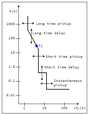
Figure 1 - Typical characteristic curve for an electronic, LV trip unit.
For relays, each section of its characteristic curve can be set to one of two profiles for time-selectivity: definite time delay (DT) or inverse definite minimum time (IDMT). For each profile, the current threshold and time delay can be adjusted. Typical profiles are shown in Figure 2.[4]
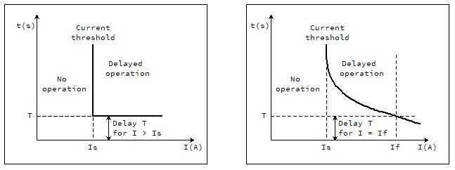
Figure 2 - Typical profiles for DT (l) and IDMT (r) MV relays.
Zones
For selectivity analysis, the trip curves are considered to consist of an "overload zone" and a "short-circuit zone", as shown on Figure 3. The overload zone is considered to be the section on the curves where the load current is 8-10 times the rated current (In) of the breaker. The short-circuit zone is considered to be currents greater than that.[5]
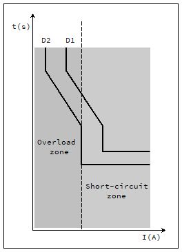
Figure 3 - Overload and short-circuit zones for series devices D1 (upstream) and D2 (downstream).
Techniques for selectivity
Various techniques can be used to achieve selectivity. In the overload zone, the time-current selectivity technique is normally employed. In the short-circuit zone, various techniques can be used including current-based, time-based and logic selectivity.
Current-based selectivity
Current-based selectivity results from the difference between the current thresholds of circuit breakers.[6] It is based on the principle that load currents and short-circuit currents are higher at devices upstream than downstream. Current-based selectivity can be achieved in both the overload and short-circuit zones. However, there is generally a limit for current-based selectivity, as shown on Figure 4.[6] To allow for manufacturing tolerances, all parts of the upstream curve must be at a greater current threshold than the downstream device by a factor of 1.35[7]
Time-based selectivity
The trip curve of any circuit protection device shows that a certain current value will cause the device to open after a certain period of time. Time-based selectivity results from an upstream device tripping after a longer period of time than a downstream device for a certain current value. To allow for manufacturing tolerances, the time difference between the upstream and downstream devices must be >300ms.[7] It can be seen on Figure 4 that time-based selectivity can extend the protection range of a device past the short circuit limit of current-based selectivity. Time-based selectivity is therefore considered to operate predominantly in the short-circuit zone.
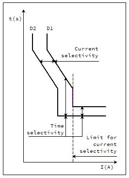
Figure 4 - Time and current selectivity between series devices D1 and D2.
Logic selectivity
Logic selectivity is used when a sufficient time difference cannot be achieved to assure time based selectivity. Each protection device activated by a fault sends a blocking signal to the upstream device that delays the opening of the upstream device by a set value, giving the downstream device time to fully open and clear the fault. When the blocking signal times out, if the fault is present at the upstream device it will in turn send a blocking signal to its upstream device, and so on.[4] Support for logic selectivity is device dependent. Cables must be used to link the devices. A general arrangement is shown in Figure 5.
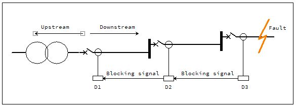
Figure 5 - General arrangement of logic selectivity.
Case study
Description
The case study is a large commercial installation with 11/0.4kV transformers connected in parallel, and fed from an 11kV parallel-feeder architecture. This report considers the selectivity between the LV circuit protection device (CPD) on the secondary side of one transformer, upstream through three MV relays to the network operator's device (the other transformers are similar). Calculation of the short-circuit currents and the selection of the CPDs is outside of the scope of the report.
System model
The path from the LV device, CB-L1, on the secondary side of one transformer, upstream to the device in the network operator's 11kV switchboard, CB-M1, was modelled in (Amtech) Protect HV. Settings for CB-M1 were supplied with the instruction that they could not be adjusted. Settings for CB-L1 were governed mainly by the installed load on its main LV switchboard. The two intermediate devices, CB-M2 and CB-M3, were initially set in the model to be equally spaced for both current and time between CB-M1 and CB-L1. This initial setup is shown in Figure 6, where current on the x-axis is at 11kV.
Selectivity study
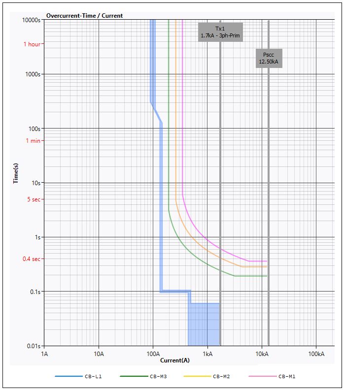
Figure 6 – Output from Protect HV model, showing initial setup.
It can be seen on Figure 6 that in the overload zone, spacing between breakers of 1.35x for current-based selectivity is achieved.
The maximum fault current at the primary terminals of the transformer is 1.7kA. Figure 6 shows that at this current, the LV breaker, CB-L1, will open in 60ms, while the network operator's breaker, CB-M1, will open in approximately 300ms. Therefore, Δt between all four breakers when equally spaced is 80ms. As referenced above, 300ms is required. Time-based selectivity is not achieved in the short-circuit zone with the setup as shown. A solution was required, and two options were investigated and presented to stakeholders.
Option 1 was to implement logic selectivity, so that each device would delay its operation by 300ms on receipt of a blocking signal from its downstream neighbour. Due to the cabling and complexity involved, this was rejected by various stakeholders.
Option 2 was to approach the network operator with a request to modify their relay settings. If CB-L1 opened due to a downstream fault, it would be due to a serious event with serious consequences, and CB-M3 opening at the same time would not make matters significantly worse. Setting CB-M3 to open at 60ms with CB-L1 in the short-circuit zone enables CB-M2 to be set at 360ms for selectivity. By increasing the opening time of CB-M1 from 600ms to 660ms provides selectivity with CB-M2. Although a compromise, time-selectivity could be achieved that protected the installation in a practical way. This solution was approved by the various stakeholders and implemented. The characteristic curves for the solution are shown in Figure 7.
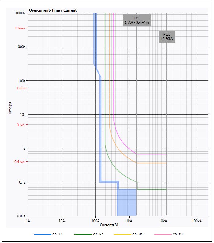
Figure 7 – Output from Protect HV model, showing final solution.
Conclusions
In real systems, current and time selectivity between all the devices in series cannot always be achieved. Unless safety would be impaired, solutions can involve compromise, based on the business requirements of the client.
References
[1] IET. BS7671: 2018. Requirements for electrical installations. Part 2, Definitions.
[2] IET. BS7671: 2018. Requirements for electrical installations. Annex A53.
[3] ABB. White paper - Working with the Trip Characteristic Curves of ABB SACE Low Voltage Circuit-Breakers. 2007
[4] Schneider Electric. Electrical network protection. 2006
[5] ABB. Technical application paper. Low voltage selectivity with ABB circuit-breakers. 2024
[6] Schneider Electric. Discrimination with LV power circuit breakers. 2001
[7] Schneider Electric. Electrical installation Guide. Ch. B, Connection to the MV utility distribution network. 2018
Contact
Enquiries are welcome from M&E contractors, consultants and renewable energy system developers.
How can we support you with your electrical design tasks?
Contact details here ...
